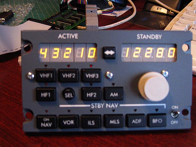
As I spend a lot of time flying on VATSIM, the radio panels are important to me to tune the radios. Up to now I have had to use squawkbox to tune them.
When I placed the first order with FDS for panels they said that they were planning to offer Plug & Play radio modules and the IBL panels were not available.By the time I needed these, FDS were still not offering anything to help me along other than some of the hardware.
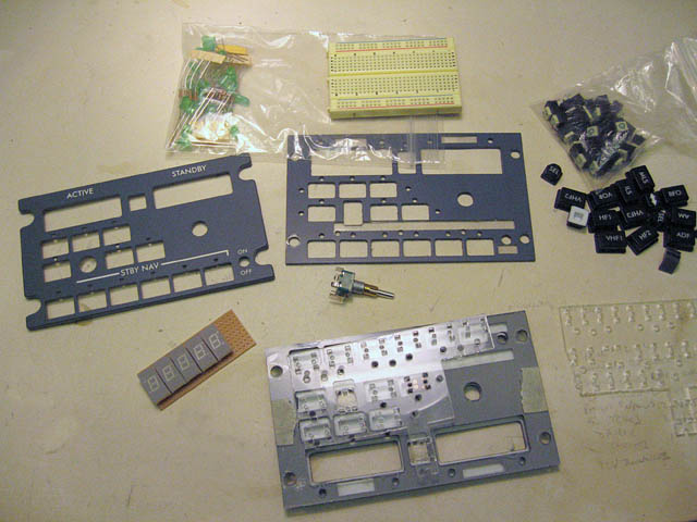
I decided I had to find another way. I managed to buy a pair of panels from another builder who had changed his plans and I bought his FDS panels. I got together the rest of the parts from various online sources.
They are not IBL panels although there are transparent windows to enable lighting to shine through. As there is so little on these panels that is backlit I decided to forego that at this time, I can always come back to it later. All of the push buttons are illuminated however so the visual appeal will be good and the colour of the panels matches the others that I have.
I made the switch mounting plates from acrylic sheet and used matrix board to mount the seven digit displays and the dual shaft encoder.
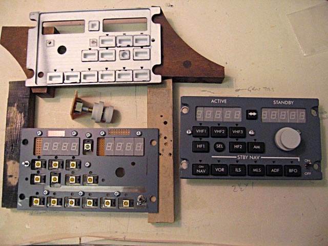
It is possible to buy mounting boards for the seven digit displays from Flight Deck Technology but they use a slightly smaller digit than the ones I planned to use which would have meant making a mask to fill the gaps. Whilst the digits on mine are the same size they are in a larger shell which fit better into the frame. The pins are in different positions so it was necessary to make my own holder using matrix board again.
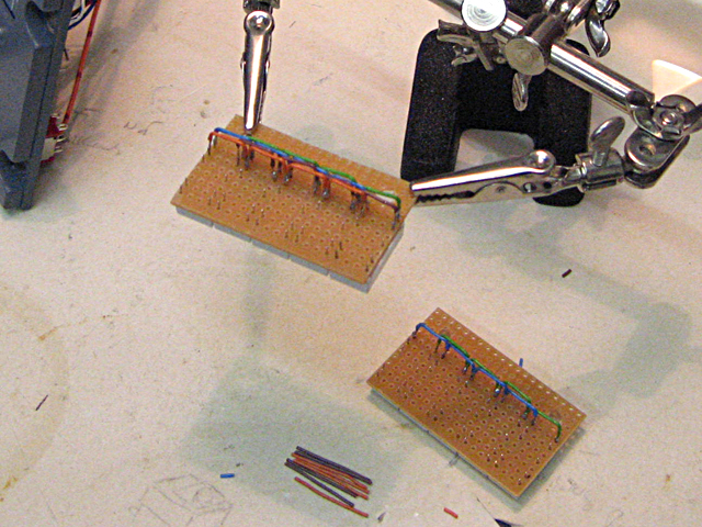
Each segment in the display is wired in series with all of the other like segments. The ground connection of each segment must be brought out separately, they cannot be ganged together.
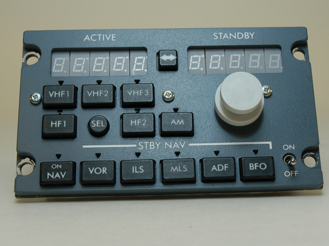
One panel is finished, the second set of seven segment displays is in hand.
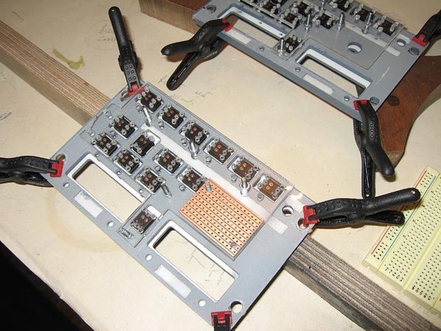
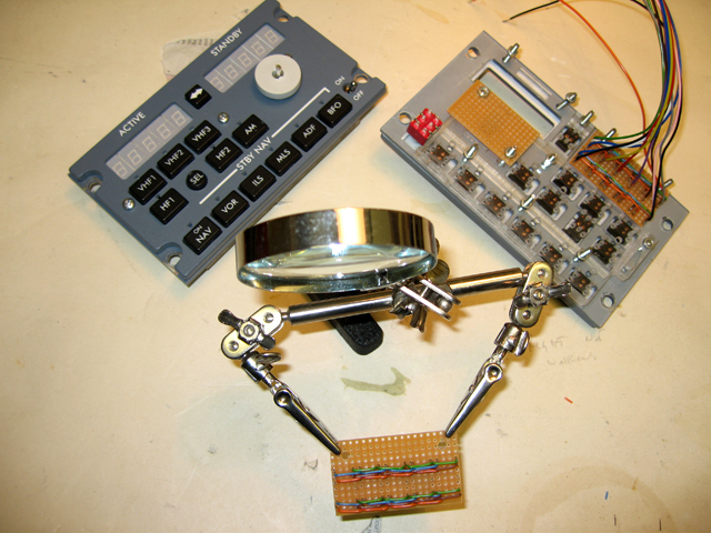
The switches are all wired here using a common busbar for the returns. The LED's in the switches are wired in series arrays to run off 12 volts; there are two five light arrays and one four light in each panel.
The encoders are wired into the "input" harness together with the switches including the one toggle.
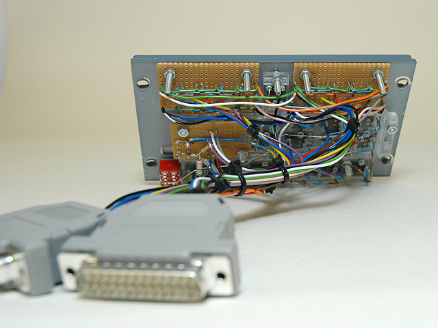
There are so many wires coming out of the displays that two plugs were necessary for the "output" harness.
I am using a lot of plug and socket breaks in my wiring so that units can be removed for maintenance.